TL;DR:
- Prioritize four diagram types—C4 component, sequence, API contract, and deployment—to effectively communicate in modular enterprise systems.
- Model interfaces first, version diagrams with code, and assign dedicated owners to prevent diagram rot during rapid development cycles.
For modular enterprise systems, prioritize four diagram types above all others: C4 component diagrams for module boundaries, sequence diagrams for business logic flows, interface/API contract diagrams, and deployment or data-flow diagrams. The single principle that prevents wasted effort is this: model interfaces first, version every diagram alongside code.
Three named standards anchor this approach:
- UML provides the standardized notation for structural and behavioral diagrams across the entire system.
- C4 model layers that notation into four abstraction levels (Context, Container, Component, Code), making it practical for modular boundaries.
- PlantUML and Mermaid let teams write diagrams as code, so they live in version control and update with every pull request.
Which software engineering diagram types should your team use?
Every diagram type has a natural audience. Choosing the wrong one for the wrong stakeholder wastes time and produces artifacts nobody reads. Diagrams succeed when each artifact has a clear audience and a defined outcome.
| Diagram Type | Primary Audience | When to Create It |
|---|---|---|
| C4 Context / Component | Architects, product managers | When defining module boundaries for a new payment or auth module |
| Sequence | Developers, QA | When validating a multi-service business logic flow before coding |
| API / Interface contract | Developers, integration teams | When two modules must agree on a contract before either is built |
| Deployment / Network | SRE, DevOps, security | When planning infrastructure topology or reviewing blast radius |
| Data model / ER | Developers, data architects | When designing shared data stores across module boundaries |
| Activity / Flowchart | Product managers, QA, business analysts | When mapping an approval workflow or SDLC decision gate |
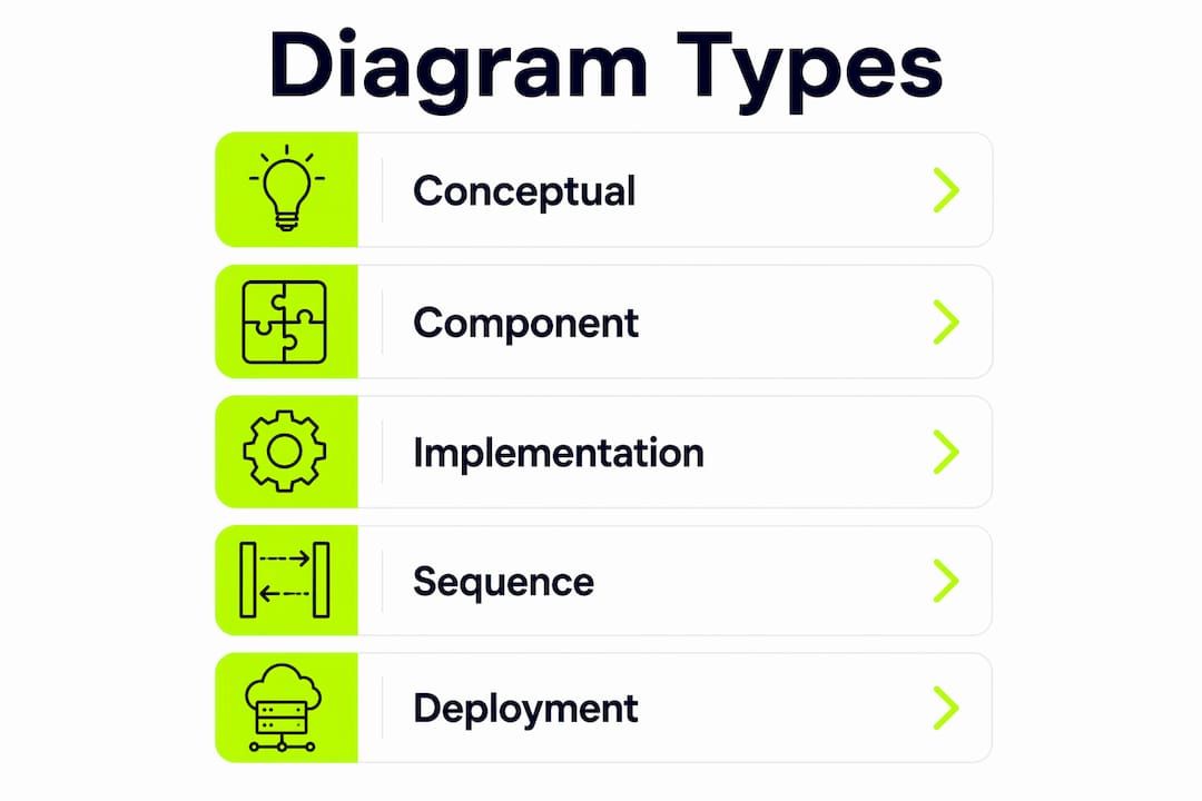
UML is a standardized visual language approved by ISO in 2005, covering both structural diagrams (class, component, deployment) and behavioral diagrams (sequence, activity, use case). It is not a programming language and does not execute. The C4 model sits on top of UML notation and provides the practical layering that modular teams actually need: a Context diagram for executives, a Container diagram for architects, a Component diagram for developers, and a Code diagram only when the implementation detail genuinely matters.
For modular component architectures, component and sequence diagrams carry the most weight. They expose integration points without forcing teams to document every internal class.
How should you structure diagrams for modular systems?
Three abstraction levels map cleanly to the stakeholders in a modular enterprise project. Getting the level wrong is the most common source of diagram rot: a diagram too detailed becomes stale within days; one too abstract gives developers nothing to act on.

Level 1 — Conceptual (C4 Context): Show the system, its users, and external dependencies. No internal modules, no technology choices. Audience: executives and product owners.
Level 2 — Component/Container: Show module boundaries, APIs, message contracts, and data stores. This is the interface-first design layer. Audience: architects and senior developers.
Level 3 — Developer/Implementation: Class diagrams, ER diagrams, and detailed sequence flows. Create these only when a specific integration or data model decision requires shared understanding. Audience: developers and QA.
The interface-first rule is non-negotiable for modular builds: APIs, message contracts, and data contracts appear as first-class items at Level 2 before any implementation begins. A common anti-pattern is jumping straight to class diagrams for a greenfield module, producing a detailed blueprint that changes three times before the first sprint ends.
Good abstraction: A C4 component diagram showing PaymentModule → [REST API] → OrderService, with the contract defined as an OpenAPI snippet.
Bad abstraction: A class diagram showing every private method inside PaymentModule before the interface is agreed upon.
Pro Tip: If drawing a diagram takes longer than building a quick prototype, it is too detailed for the current phase. Prefer lightweight component and sequence sketches early; add implementation detail only when the interface is stable.
Ownership matters as much as content. Architects own Level 1 and Level 2 diagrams; developers own Level 3 and sequence diagrams for their modules. Update cadence: Level 1 diagrams update at major milestones; Level 2 and Level 3 update with every sprint that changes an interface. Assign a named owner in the diagram file header, not just in a wiki.
Which tools and workflows prevent diagram rot?
Failing to update diagrams after code changes is the primary cause of diagram rot. The fix is structural: diagrams must live where code lives, update when code updates, and be reviewed in the same pull request.
The core selection criteria for any diagramming tool in a modular enterprise context:
- Diagram-as-code support (text-based source that can be diffed in Git)
- VCS/CI integration (GitHub Actions, GitLab CI, or IDE plugins)
- Real-time collaboration and comment threads
- Support for UML, C4, sequence, and deployment diagram types
- Export formats: SVG, PNG, HTML, and JSON
- Enterprise features: SSO, audit logs, role-based access
Tool landscape:
- PlantUML: Text-based, generates UML and non-UML diagrams from a simple DSL. Integrates with CI pipelines and IDEs. The go-to for teams that want full diagram-as-code with broad diagram type coverage.
- Mermaid: Markdown-native flowchart and sequence diagram support. Renders directly in GitHub, GitLab, and Notion. Ideal for lightweight sequence and flowchart diagrams embedded in READMEs and ADRs.
- Structurizr: Purpose-built for the C4 model. Supports the Structurizr DSL for code-driven C4 diagrams with workspace versioning. The strongest choice when C4 is the team’s primary architectural notation.
- diagrams.net (draw.io): Free, open-source visual editor with XML-based source files that can be committed to Git. Supports UML, C4, ER, and network diagrams. Works offline and integrates with Confluence and Google Drive.
- Lucidchart: Web-based visual editor with real-time collaboration, comment threads, and Lucid’s Smart Shapes for UML. Strong enterprise features including SSO and audit logs. Less native diagram-as-code, but supports import/export of structured formats.
- Microsoft Visio: The incumbent in large enterprises. Deep integration with Microsoft 365 and SharePoint. Supports UML and network diagrams but has limited diagram-as-code capability and no native Git integration.
| Tool | Diagram-as-Code | VCS/CI Integration | Real-Time Collaboration | UML / C4 / Sequence | Export Formats | Enterprise Features |
|---|---|---|---|---|---|---|
| PlantUML | Native (DSL) | Strong (CI plugins, IDE) | Limited | UML, sequence, C4 via extension | PNG, SVG, PDF | Self-hosted, no SSO |
| Mermaid | Native (Markdown) | Native (GitHub/GitLab) | Via host platform | Flowchart, sequence, ER | SVG, PNG, Mermaid code | Via host platform |
| Structurizr | Native (DSL) | Strong (workspace API) | Limited | C4 native | PNG, SVG, PlantUML | Cloud and on-premise |
| diagrams.net | XML source in Git | Manual commit | Limited (async) | UML, C4, ER, network | SVG, PNG, HTML, XML | Confluence plugin |
| Lucidchart | Limited | Via export/import | Real-time, comments | UML, C4, sequence | SVG, PNG, PDF, Visio | SSO, audit logs |
| Microsoft Visio | Limited | SharePoint/OneDrive | Co-authoring | UML, network, flowchart | SVG, PNG, PDF, VSD | SSO, enterprise DLP |
Workflow patterns that prevent rot: store diagram source files in the same repository as the code they describe; add a CI step that renders diagrams on every PR and fails the build if source and rendered output diverge; use IDE plugins (PlantUML for VS Code, Mermaid Preview) so developers see diagram changes before committing. Automating diagram updates through VCS integrations reduces manual maintenance overhead and keeps documentation honest.
How Bitecode keeps diagrams current during modular builds
The workflow below reflects how Bitecode structures diagram work across a rapid modular delivery cycle, balancing forward and backward design so diagrams stay useful rather than decorative.
- Discovery (Day 1–2): Identify module boundaries and external dependencies. Produce a C4 Context diagram. Owner: solution architect.
- Interface-first C4 sketch (Day 2–3): Draft a C4 Component diagram for each module, marking every API and message contract. No implementation detail yet.
- Sequence validation (Day 3–5): Write sequence diagrams for the two or three highest-risk business logic flows. These diagrams are reviewed by QA and product before any code is written.
- Prototype implementation (Sprint 1): Developers build against the agreed interfaces. Diagram source files live in
/docs/diagrams/alongside code. - Automated diagram generation (ongoing): Where possible, generate ER diagrams and deployment diagrams from annotations or infrastructure-as-code. PlantUML or Mermaid scripts run in CI.
- PR-based diagram updates: Any PR that changes an interface must include an updated diagram file. Reviewers check diagram accuracy as part of code review. Teams that store diagram source alongside code reduce diagram rot and improve onboarding speed.
- Release-time backward documentation: At each release, the team audits Level 2 diagrams against the running system and updates any drift. This is the backward design pass.
Initial sketches are complete within the first week. Ongoing updates happen with every sprint that touches an interface. The enterprise system design workflow follows the same cadence for governance and review.
Pro Tip: Bitecode reduces turnaround between a diagram change and deployment by treating diagram files as first-class PR artifacts. A diagram that cannot be reviewed in a PR does not belong in the repository.
A practical checklist and templates for your most-used diagrams
Every diagram file in a modular project should carry these fields in its header:
- Title: descriptive, including the module name
- Owner: named individual or team
- Last updated: date and sprint number
- Version tag: matches the code release it describes
- Interfaces listed: all APIs and contracts shown explicitly
- Security/data-flow highlights: sensitive data paths marked (e.g., PII, payment data)
Minimal C4 component snippet (PlantUML):
@startuml
!include C4_Component.puml
Component(paymentModule, "Payment Module", "Handles transactions")
Component(orderService, "Order Service", "Manages orders")
Rel(orderService, paymentModule, "POST /payments", "REST/HTTPS")
@enduml
Minimal sequence diagram (Mermaid):
sequenceDiagram
  Client->>OrderService: POST /orders
  OrderService->>PaymentModule: POST /payments
  PaymentModule-->>OrderService: 200 OK {transactionId}
  OrderService-->>Client: 201 Created {orderId}
Minimal API contract snippet (OpenAPI fragment):
paths:
  /payments:
    post:
      summary: Initiate payment
      requestBody:
        required: true
        content:
          application/json:
            schema:
              $ref: '#/components/schemas/PaymentRequest'
Review cadence and branching: diagram branches should mirror code branches. A feature branch that introduces a new API gets a diagram update in the same branch. Merge the diagram with the code, never after. For modular monolith architectures, this discipline prevents the most common failure mode: a deployed interface that no diagram reflects.
The process improvement principles that govern change control in complex projects apply directly here: document the change, assign an owner, and close the loop before the next release.
| Review Trigger | Diagram Types Affected | Owner | Cadence |
|---|---|---|---|
| New module or API | C4 Component, Sequence, API contract | Architect + developer | Before sprint coding begins |
| Interface change | Sequence, API contract | Developer | Same PR as code change |
| Infrastructure change | Deployment, Network | SRE / DevOps | Same PR as infra change |
| Data model change | ER diagram | Data architect | Same PR as migration |
| Major release | All Level 2 diagrams | Solution architect | Release review meeting |
Key Takeaways
Interface-first C4 diagrams versioned alongside code are the single most effective way to prevent diagram rot in modular enterprise systems.
| Point | Details |
|---|---|
| Prioritize four diagram types | C4 component, sequence, API contract, and deployment diagrams cover most modular team communication needs. |
| Model interfaces before implementation | Define APIs and message contracts at Level 2 before any developer writes code for a new module. |
| Version diagrams with code | Store diagram source in the same repository and require diagram updates in every PR that changes an interface. |
| Assign named owners and cadence | Each diagram has one named owner; Level 2 diagrams update every sprint that touches an interface. |
| Bitecode’s workflow | Bitecode uses interface-first C4 sketches, PR-based diagram reviews, and automated generation to keep diagrams accurate across rapid modular delivery cycles. |
Why interface-first diagrams are the real differentiator
The conventional wisdom treats diagrams as documentation, something produced after the system is built to satisfy an audit or onboard a new hire. That framing explains why most enterprise diagram libraries are out of date within a quarter. The more productive framing is that a diagram is a contract negotiation tool. A C4 component diagram drawn before a single line of code is written forces the team to agree on module boundaries, API shapes, and data ownership. That agreement is worth far more than any post-hoc documentation pass.
The teams that get the most value from diagramming are not the ones with the most detailed diagrams. They are the ones who treat diagram-as-code as a first-class engineering practice, the same way they treat automated testing. A diagram that cannot be diffed, reviewed, and merged is a liability, not an asset. The shift from “draw it in a shared drive” to “commit it to the repo” is small operationally but significant in terms of how quickly integration defects surface. Faster onboarding and fewer integration surprises are the practical outcomes, not abstract benefits.
From diagrams to deployed modular systems
Bitecode starts every custom enterprise build with up to 60% of the baseline system pre-built using modular, ready-made components, which means the interface-first diagrams described in this guide translate directly into working code rather than sitting in a backlog. The gap between a C4 component sketch and a running prototype is measured in days, not months, because the modular foundation already handles AI automation, financial processing, and workflow orchestration.
For teams that need to move from architecture diagrams to a deployed system without rebuilding boilerplate from scratch, Bitecode’s custom software development service is the direct path. Teams that want to automate diagram generation and integrate it into their CI pipeline can explore Bitecode’s AI process automation service. Contact Bitecode to scope your modular build and get a working prototype in front of stakeholders within weeks.
Useful sources
- UML Introduction — GeeksforGeeks: Comprehensive reference for UML diagram types, ISO standardization history, and structural vs. behavioral diagram categories. Start here for notation fundamentals.
- Chapter 4: Models — Software Engineering: A Modern Approach: Academic treatment of UML as sketch vs. blueprint, covering class, package, sequence, and activity diagrams with worked examples. Useful for teams establishing diagram standards.
- C4 Model — Structurizr: The canonical resource for C4 architectural notation, including the DSL reference and workspace examples for modular systems.
- PlantUML: Official documentation for the PlantUML DSL, covering all supported diagram types and CI integration options.
- Mermaid Studio docs: Reference for Mermaid flowchart and sequence diagram syntax, with IDE plugin guidance.
- diagrams.net (draw.io) — Software Design Use Cases: Practical guidance on diagram types for software design, forward vs. backward design, and VCS integration patterns.
- Microsoft Engineering Fundamentals Playbook — Diagram Types: Microsoft’s internal engineering guidance on diagram selection, abstraction levels, and interface-first design for modular systems. One of the most practical references available publicly.
- Miro — Types of Diagrams: Broad overview of diagram types as communication tools, with audience and use-case mapping.